

01 · Measure
Distance calculation
Odometry tracked the robot's field position. The distance formula compared that pose with the fixed GOAL coordinates.
FIRST Tech Challenge · 2025–2026
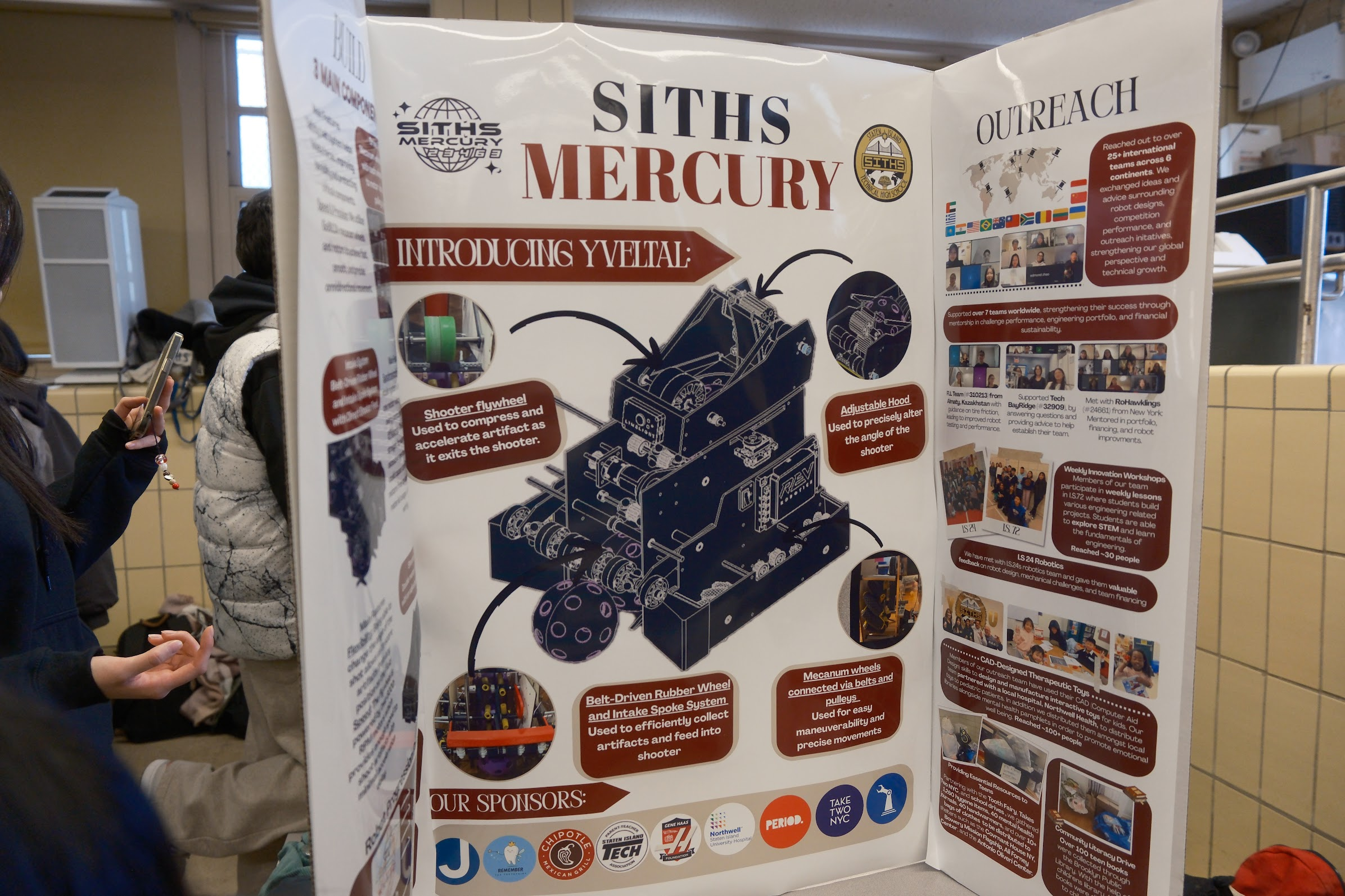
Three robot iterations led to this compact turreted design for the NYC Championship.
Season
Three complete robot iterations
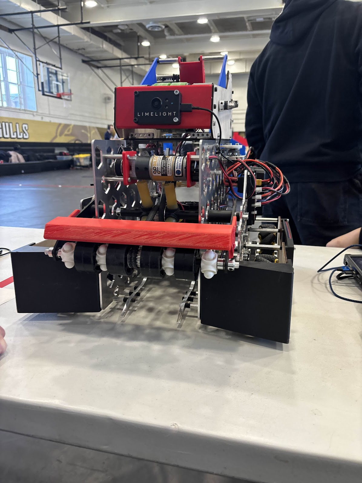
Final robot
Bumper intake + servo turret
Season finale
NYC Championship
The challenge
In the 2025–2026 game, robots collect purple and green ARTIFACTS, launch them into a GOAL, and use their colors to complete patterns.
Official DECODE overview ↗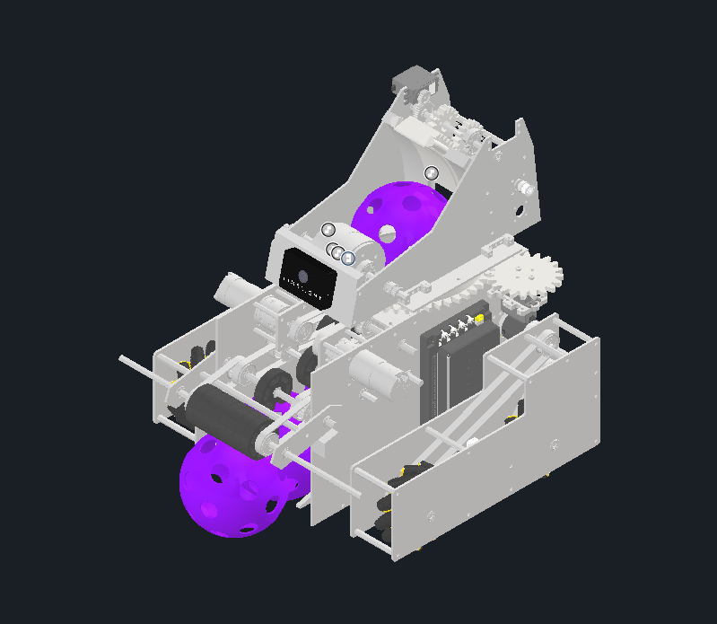
Game pieces
Purple and green ARTIFACTS
Main task
Collect, aim, and launch into the GOAL
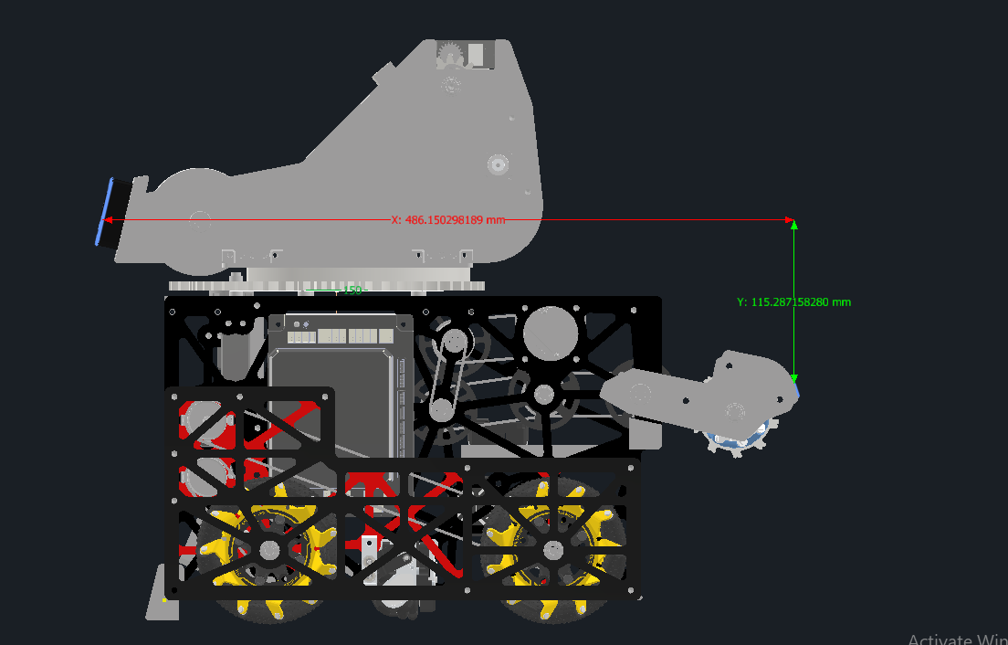
Size constraint
Fit inside an 18 × 18 inch footprint
Shared shooter control
Every robot used the same core shooting strategy. Field position determined the distance to the GOAL, testing converted that distance into a target flywheel RPM, and closed-loop control kept the flywheel near that speed.
01 · Measure
Odometry tracked the robot's field position. The distance formula compared that pose with the fixed GOAL coordinates.
02 · Select
Repeated shooting tests produced a regression that mapped distance to the flywheel speed needed for a repeatable shot.
03 · Correct
Encoder feedback measured actual RPM. PID continuously adjusted motor power to reduce error and recover after each launch.
Measured flywheel response
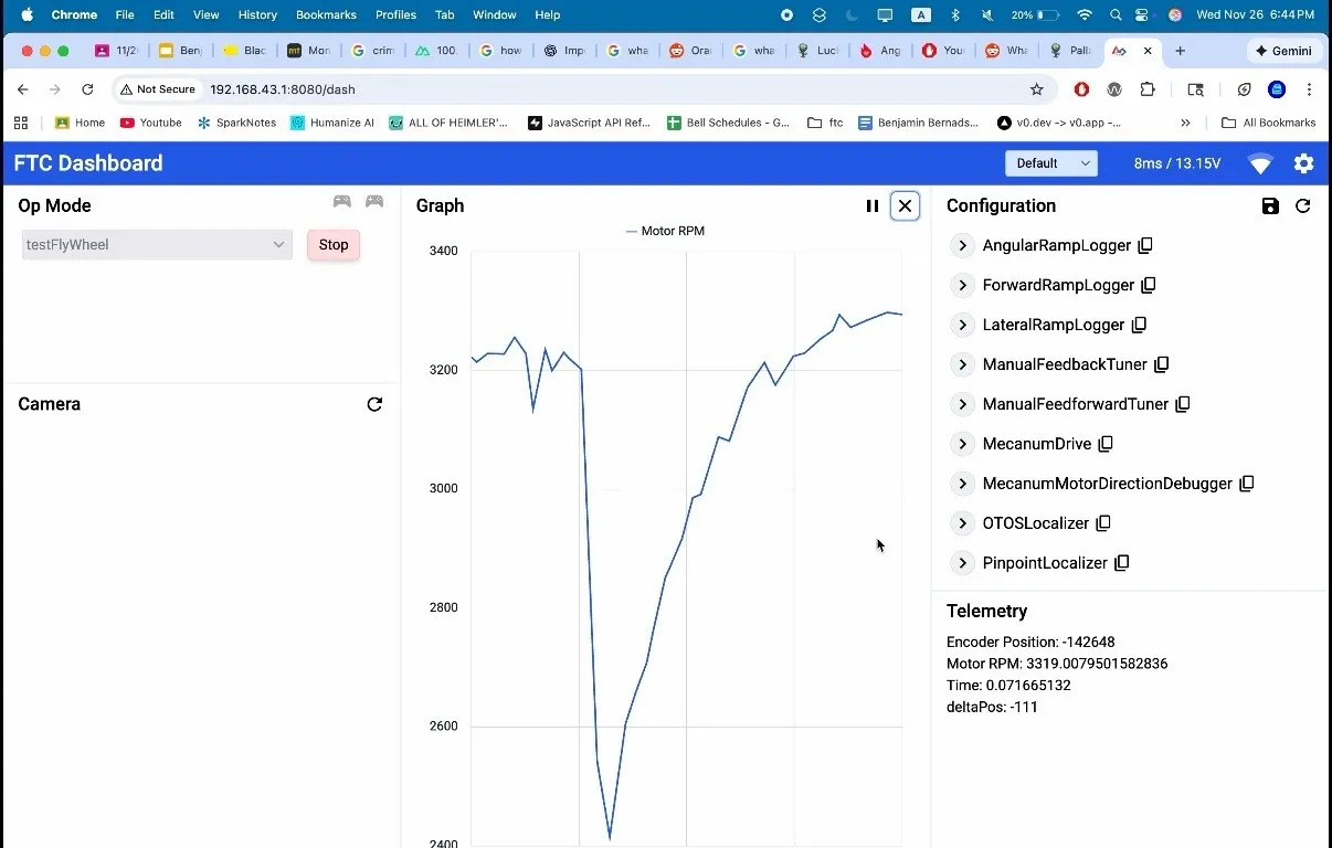
Closed-loop flywheel control
Robot version 01
The first robot tried to create one continuous path from the floor to the GOAL. It combined a rubber-band intake, sideways centering, a kicker, a flywheel shooter, and an AprilTag-guided turret.
Collect
Pulled ARTIFACTS in from the floor
Center
Moved each ball sideways into the firing path
Lift
Tried to push the ball upward
Launch
Single-motor wheel with an adjustable exit angle
Aim
Arducam, AprilTags, motor, and gear ring
What testing exposed
Problem
The rubber bands stretched, tangled, and failed at useful intake speed.
Response
We temporarily installed shorter bands, then treated the intake material and geometry as a redesign priority for the next robot.
Problem
The vectored wheels did not compress the ARTIFACT enough to center it quickly.
Response
The slow sideways transfer showed that passive wheel angle was not enough without controlled compression.
Problem
The servo kicker could not give the ball enough energy to reach the main flywheel.
Response
We replaced it with a motor-driven feeder wheel that could shoot the ball upward into the main shooter.
Problem
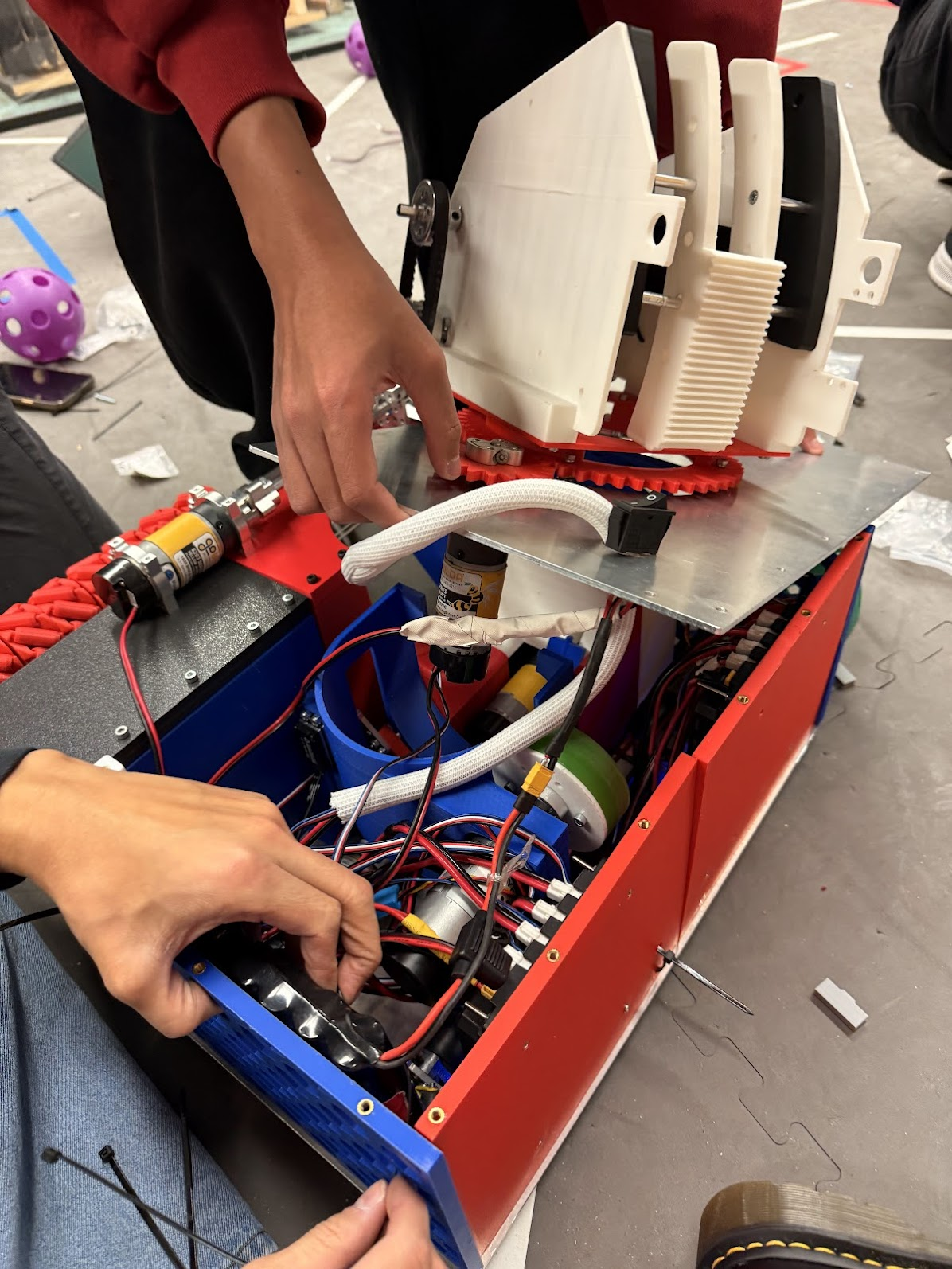
The rotating turret cable could extend beyond the legal 18 × 18 inch footprint.
Response
We zip-tied the cable down as a temporary competition fix and carried cable management into the next design.
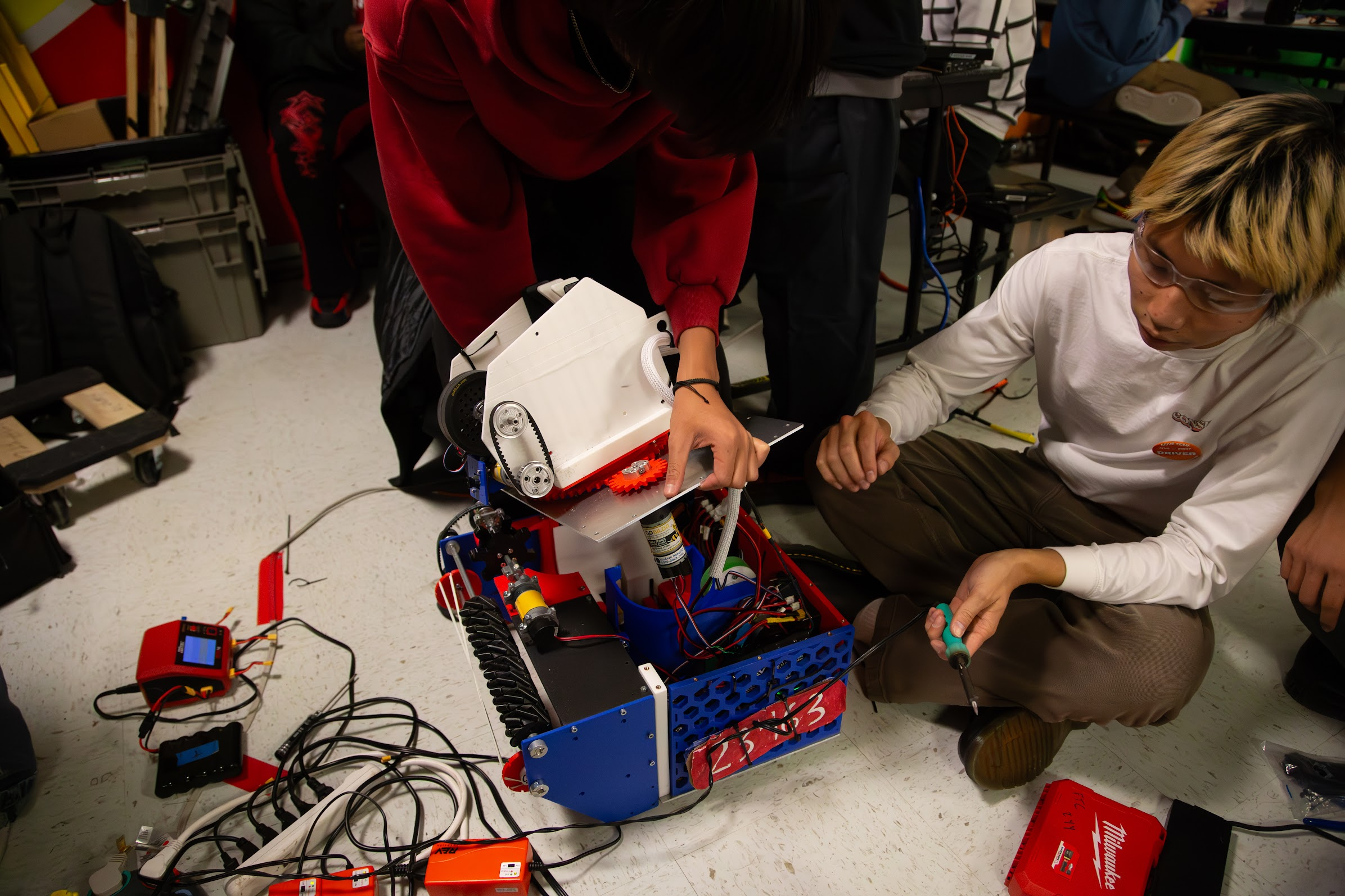
Turret test
The front Arducam scanned for AprilTags, and a geared motor rotated the shooter turret to face the target. The same rotating assembly also created a cable-management problem that pushed the robot outside its legal footprint.
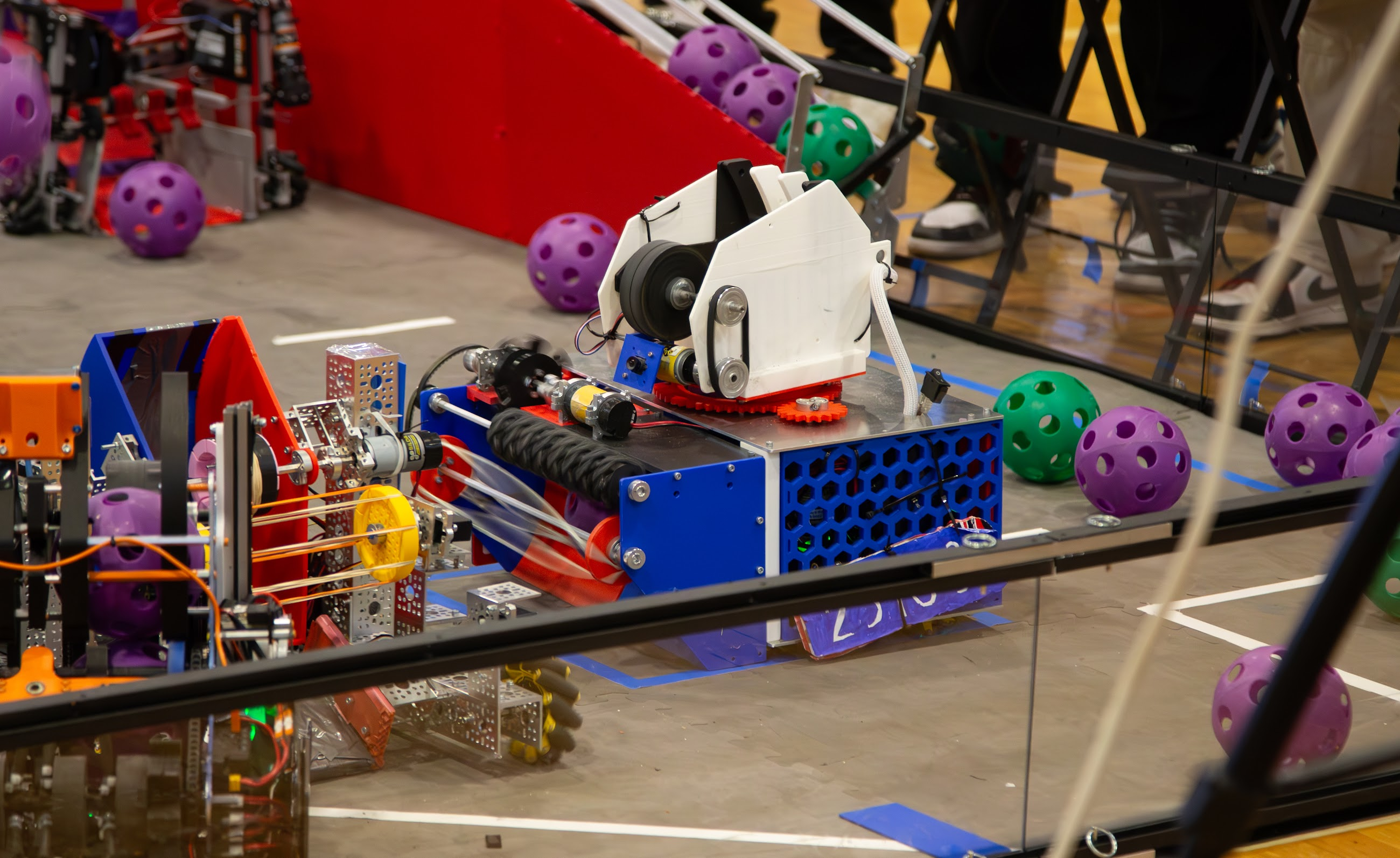
Robot version 02
The second robot addressed the first intake's reliability and compression problems. It kept the same basic shooting idea, but doubled the shooter motors and temporarily traded the turret for field-oriented chassis aiming.
A time crunch shaped this version: removing the turret simplified the build, but moved a much larger part of the aiming problem into code.
Collect
Pulled ARTIFACTS in without stretchable bands
Guide
Centered off-axis pickups toward the shooter path
Buffer
Stopped the direct intake from feeding too early
Launch
Smaller hood with faster RPM recovery
Aim
Odometry, trigonometry, regression, and Limelight
Problem
A rigid intake made the chassis bounce over the ball.
Floating response
The vectored-wheel assembly could rise through a limited range.
Remaining issue
The intake still could not reliably reach the funnel's outer edges.
Version 1 → Version 2
System
Intake
Changed
Rubber bands became direct-drive rubber wheels.
Why
The first bands stretched, tangled, and failed at useful speeds.
Result
A more positive intake path without elastic bands.
System
Compliance
Changed
The vectored-wheel assembly gained limited upward travel.
Why
A rigid intake transferred the ball impact into the chassis and made the robot bounce.
Result
The intake rose over the ARTIFACT while the chassis stayed planted.
System
Shooter
Changed
A smaller adjustable hood and a second flywheel motor.
Why
The shooter needed to reach and recover its commanded RPM faster.
Result
Much faster spin-up while keeping PID speed control.
System
Aiming
Changed
The turret was temporarily removed and the whole chassis aimed instead.
Why
The team was time-crunched and could not finish the turret for this version.
Result
Odometry and field geometry calculated the heading and shot speed.
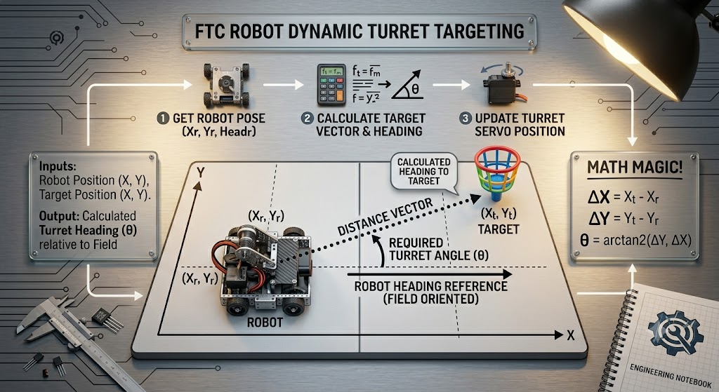
Field-oriented targeting
Vision
Version 2 moved from the Arducam to a Limelight for higher-frame-rate AprilTag scanning. Vision supplemented the robot pose used by the field-oriented targeting code.
Autonomous
By this version, the robot also had an autonomous routine built with Road Runner for the autonomous period of each match.
What still failed
The funnel helped guide off-center ARTIFACTS, but the outer sections extended beyond where the intake wheels could reliably grab them. Compliance solved the bounce problem without fully solving pickup coverage.
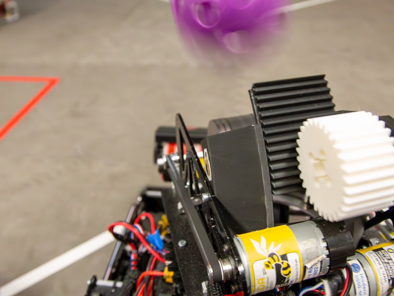
Rapid-fire test
This portrait test clip belongs here because it shows the combined result of the trapdoor, direct feed, dual-motor flywheel, and PID recovery between shots.
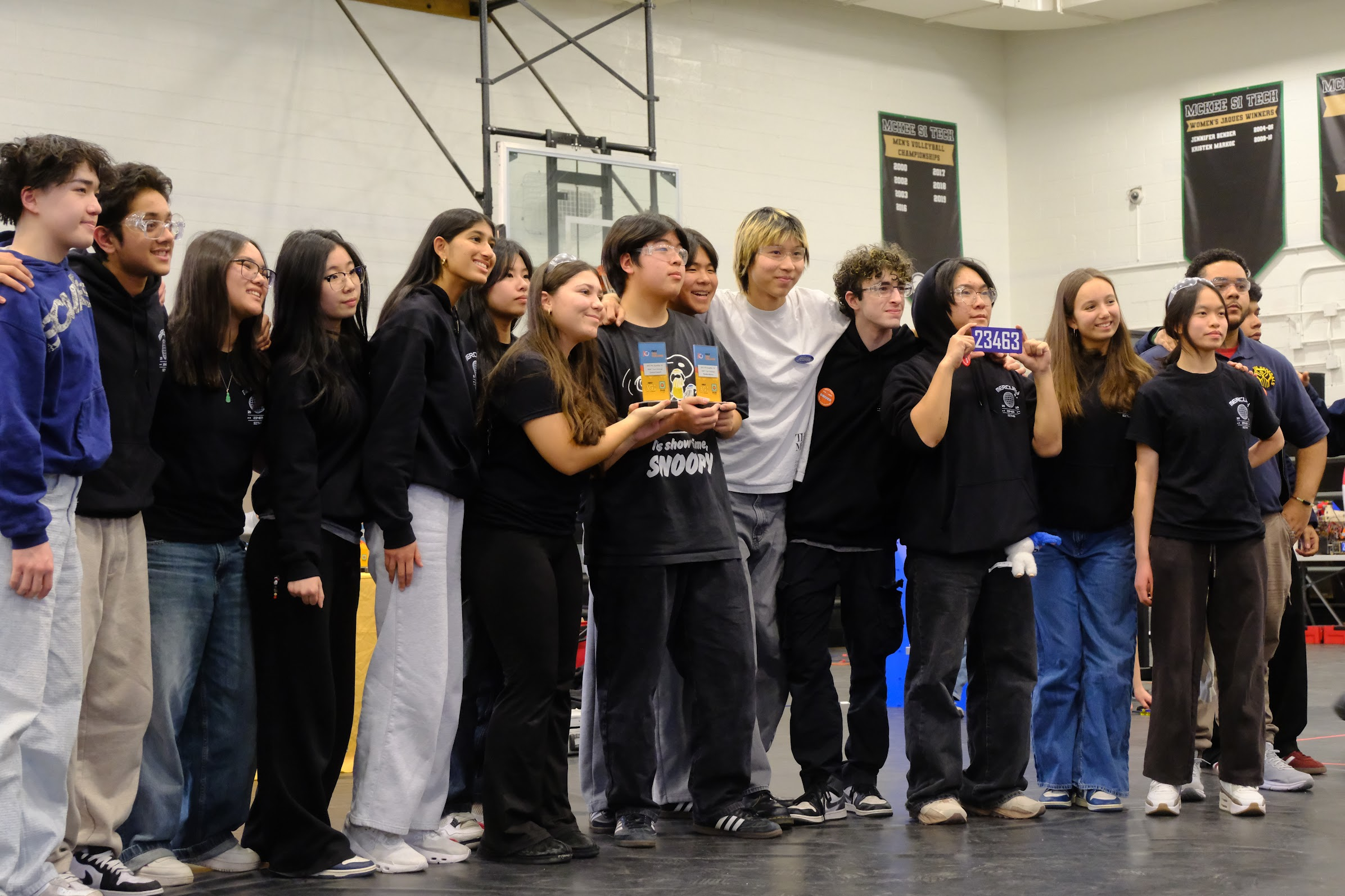
Competition result
2nd
This version carried us through the Super Qualifier bracket and into the final, where we finished in second place.
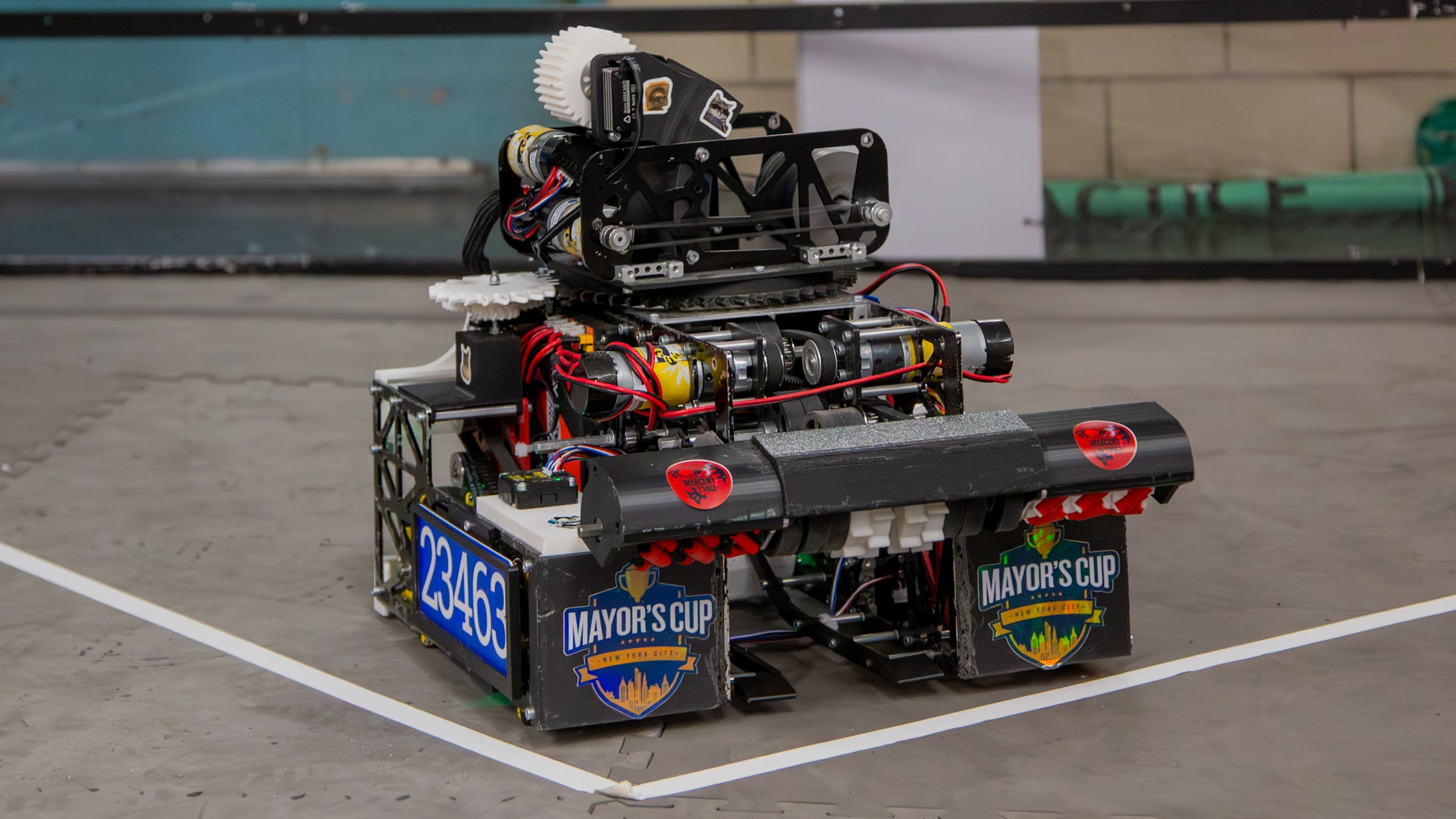
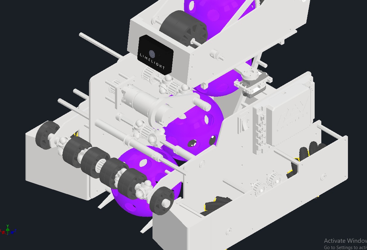
Robot version 03 · Final
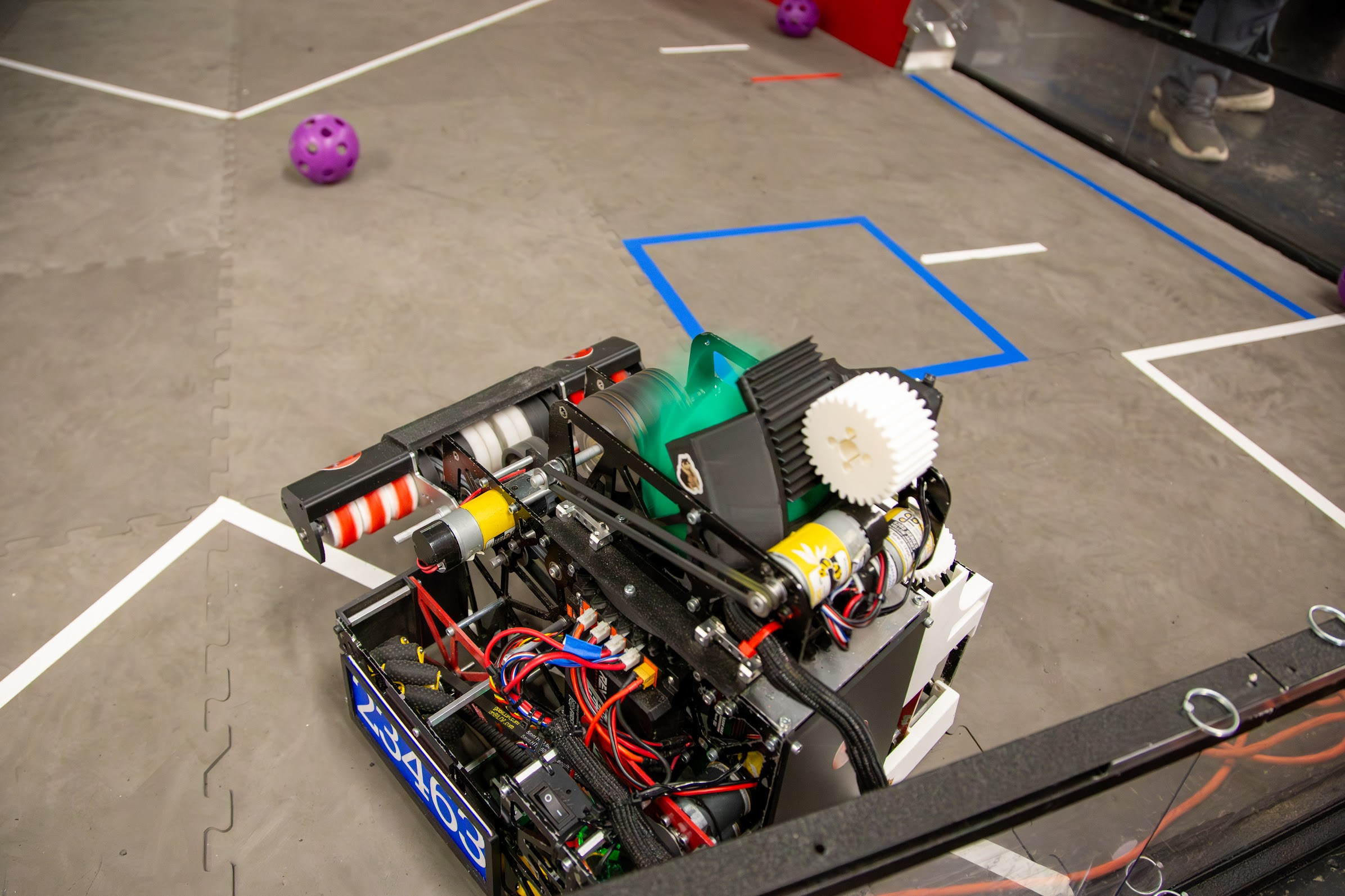
Our final robot kept Version 2's floating direct intake, trapdoor, dual-motor shooter, and odometry. It replaced the funnel with bumpers, returned to a turret, and compressed the drivetrain packaging for the robot we brought to the NYC Championship.
This was our most complete design of the season. We performed well at the championship, but our season ended there rather than advancing to Worlds.
Collect
Kept the direct-drive intake and controlled compliance
Guide
Deflected impacts without pushing ARTIFACTS away
Buffer
Retained ARTIFACTS until the shooter was ready
Launch
Kept fast spin-up, PID control, and adjustable exit angle
Aim
Servo-driven 1:1 modular gears with no camera
Version 2 → Version 3
System
Ball guidance
Changed
The funnel became low-profile bumpers around the vectored wheels.
Why
Ball impacts against the funnel could push ARTIFACTS away before the wheels established contact.
Result
The bumpers allowed a smoother path into the same vectoring mechanism.
System
Aiming
Changed
A servo-powered turret returned with modular gears at a 1:1 ratio.
Why
Rotating the whole chassis limited driving and shooting to the same heading.
Result
The shooter could track the GOAL while the drivetrain faced or moved elsewhere.
System
Localization
Changed
The turret relied on odometry without a dedicated aiming camera.
Why
The field pose already supplied the geometry needed to calculate the GOAL angle.
Result
The Version 2 targeting math moved from chassis control to turret control.
System
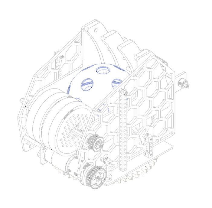
Packaging
Changed
The drivetrain motors moved toward the rear of the chassis.
Why
The final robot needed less crowded space around the intake and rotating assembly.
Result
A smaller overall robot with cleaner mechanism placement.
Camera-free targeting
The robot already knew its field pose and the GOAL's fixed coordinates. The same trigonometry from Version 2 now produced a turret angle instead of a chassis heading, so the drivetrain could keep moving independently of the shot direction.
NYC Championship
Version 3 combined the best working ideas from the season and gave us independent intake, driving, aiming, and shooting at the championship level.
Season takeaway
The final design was not one sudden breakthrough. It combined the intake compliance, trapdoor, flywheel control, odometry, and packaging lessons earned across the first two robots.